Tuesday, 1 August 2017

RKDE53 kit bumper install

The bumper is the first part of the kit, it will be followed by a GP style skirt already in the making and then a rear R56 style bumper. All of which I am quite excited about and then on to other kits potentially...

Each bumper I make is tested on a vehicle and is also measured to several key points to make sure this will fit, I hate the bad name people have given to GRP because of poor molding techniques and bad storage or items which have been made in a rush.
Every part I make has time and experience into each item, however with every hand made item you need to check and double check but no modifications are needed with the exception of adding fixing holes, 2 at the bottom to go into the front wheel arches and 2 at the top of the wheel arches, the holes for the main fixings are already in place.

As part of the test fit I tried the grills in place to be sure they sit OK which they do and there is no need to trim any structure of the car to make the bumper fit. On mine it is different but on all normal cars the bumper fits with no issues.


Happy that the bumper aligns with everything I gave the bumper a quick key with a scotch pad and set about spraying with an etch primer. This was followed by a high build primer, guide coat and then a base and clear. The prep work was simple and easy. Just the way I intended


 Once painted I put it on the car so I could admire the work gone in, I had to get the grills in...


There are several ways to attach the grills, one method is to sand the lip on the bumper on the inside until it is thin enough to allow for the grills to push on or the other method which is what I chose, remove the upstand lip all the way around the grill and the light housing so just a flat is left.
Cover the flat edge with a good PU adhesive like tiger seal etc and then push them into the bumper and hold into place for several hours - I turned the bumper over and used a can of paint as the ballast but I could have used tape to pin it but the paint was only hours old.


Bumper installed but I can't close the bonnet because I know the cable has snapped and getting in last time was a horrid experience I do not want to go through again...


A lot of people have asked what I am going to do with the lights? well there are several solutions;
  • Use the DRL kit in the headlights for side lights and have the indicator in the in the lower globe using the 501 bulb as the indicator and the H8 as the fog
  • I could use the DRL as the indicator and then keep the fog and side light at the bottom
  • The option I am going for at the moment is to use an amber LED H8 bulb for the indicator where the fog light was, and I will keep the 501 bulb as another side light as well as the DRL lights but over time this may change??
To make the 501 lights work you will need to add some cables which can be purchased from mini, I got mine from Cotswald mini for just under £10 delivered 

  • 61 13 0 006 624 (X 4) 
  • 61 13 8 373 332 (X 2)

You will also need to convert the lights for the fog or whatever you will use it for, for this just use a typical H8 connector which can be purchased from ebay or similar


Monday, 31 July 2017

RGB LED headlight cluster installed

I've gone an installed my LED conversion into the car and I am really pleased with the results;
My plan is to run the lights as white DRL but as I designed the kit I decided to allow for the functionality of any colour, why not...

Videos of the lights on with the LEDs running


The kit I have is running the bluetooth controller and because I have an android headunit I can control the lights from the headunit.
The lights once setup will remember their setting so each time the car is started it will return to the last setting.

The lights are connected to the side lights so I have some control over the lights but I may change this to an ignition point as I also have LED side lights in the bumper

Some photos of the colours


Where can you get the kit? head over to my shop or get in touch with me

Friday, 12 May 2017

RGB LED headlight cluster

Back in 2007 myself and a friend started to talk about the option of lighting the ring around the outside of the xenon lights, well we knew what we wanted to do but the reality is we just didn't do it.
Years later I wanted to do the conversion on my car but I wanted to do it properly.

I have seen other attempts to glue the LEDs into the surround with mixed success. So I took my headlights apart and laser scanned the globe area back into my CAD system which allowed me to design a holder that fits within the headlight.


I then 3D printed the holder, installed the correct light lenses and RGB LEDs which are IC controlled so can remember the colour and operation saved. This packaged up with a controller and PSU means ultimate control of how the LEDs respond. I have tried a few controllers and I have been using a bluetooth controller which means I can control the light colour from my phone.
I have even tried using a small Arduino nano to control the colours so they could go from white to amber for indicators but when the xenons are on it is difficult to see the amber light

Lights on, number 1 light is on the inside of both the clusters so they move as an opposite to each other

Couple of videos of the lights running


Simple clean design which simply snaps into the headlight housing and then just run the wires back to the controller and power.

Since the first iteration of the design I have made several small changes which has led me to the kit below, if you are interested in the kit I can do it as an assembled option or as an assembly option (For this you will need to solder 6 wires on the small PCB and will need a good small soldering iron)

Should you wish to buy a kit contact me through the site / facebook. I will be adding a shop on this site soon for some of the smaller items I already make so if that is running go for it...

* Self assembly soldering with RF remote controller
* Assembled with RF remote controller
* Self assembly soldering with BT controller and mobile phone app
* Assembled with BT controller and mobile phone app
See store if you would like to buy a unit

> All kits come with all the wire required to wire into the car and a small guide


Monday, 8 May 2017

Piersburg coolant pump

When looking at electric water pumps what direction do you take?
Davies craig, EMP, take the market for the majority but both have stigma of reliability issues, I can't confirm any whispers as I have not had any issues with either. Now with more start stop and hybrid vehicles on the road there are more electric pumps released from the factory.
Factory pumps seam to offer more and feel a lot more robust and I got quite excited to give a BMW piersburg pump a run

Why would you run an electric coolant pump?
Well for me it gives me ultimate control over the coolant system, normally if a mechanical pump is fitted it can only run as quick as the engine goes however with electric I can have the pump at maximum speed while the engine is at idle or if the temperature is low I can choose to run the pump speed slow to help raise the temperature.
Another feature is power loss at the crank which would be seen from the mechanical pump however don't be fooled I still need to power this pump but releasing the pump from the belt may see a little more power but I am not convinced you would see it.

 The water pump is a CWA200 from a BMW 118 and has the following specification;
* Pump duty point Q=7000 l/h / H=0,45 bar
* Ambient temperature -40°C ... +140°C
* Coolant temperature -40°C ... +128°C
* Voltage supply min. 10 V max. 18 V
* Power consumption P1 200 W
* nominal Current 16 A
* Quiescent current 6000 h
* Interface PWM
* Enclosure IP 67

If you wish to control using the vipec use the GP PWM and you will need to setup a control duty cycle too to give a good control. Using the Vipec I have had to add extra wires to the unit to control a relay and have an aux pwm for the water pump

The PWM frequency is 45Hz to 1100Hz

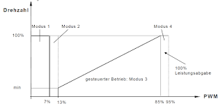
PWM operation is relatively typical
* 1~7% = Uncontrollable default to max speed
* 7~13% = 0 speed motor stopped
* 13~85% = 13% Minimum speed, 85 is maximum speed linear clime in rpm
* 85~99% = maximum speed

There is a tolerance of 1% so ideally a minimum speed would be 15% and maximum is fine at 85%, if you wish to stop the pump pick something like 10% to be far enough away from uncontrollable and minimum speed.

If you wish to only run the pump at maximum the you can run at 100% PWM which is technically just 12vDC

Running the pump at 100rpm makes filling the coolant system super easy as the header tank becomes a vacuum so as long as you can fill it fast enough you will be fine else it will suck air through once primed. The pump at 100% can just about open the thermostat which is less than ideal however you would not normally be running 100% unless you need to up the cooling and hence the thermostat would be open. (it only just opens as you can hear it fluttering)

Pin 1 Positive 12v
Pin 2 PWM signal
Pin 3 Not required
Pin 4 round

Wires, make sure you use the correct wires, I would suggest that the pump could reach a maximum of 15amps from my testing so make room for up to 30amps and add a fuse to the system. The PWM cable can be small 0.5mm^2 would be fine

For the connector I popped to BMW and ordered the correct connector and pins which made life much easier

If you wish to test or run the pump then connect positive to pins 1, 2 and ground to 4 and the pump will take a couple of seconds and will come to life.
Clearly if you wish to control the pump then you will want to use a PWM controller, I am using the Vipec and I have setup rules to control the pump based on rpm vs engine coolant temperature however I have several over riding conditions which will allow the pump to go to full speed this includes a small switch which allows me to bleed or fill the coolant system without the engine being on.

As for mounting the pump I do not have a lot of room and I took the AC delete pulley and removed all the idle bearing and bits not required until I was left with basically a mounting plate, I then made a strap bracket to fit the shape of the pump. I added anti vibration rubber round the pump and clamped it into place. It is worth noting that I cut off all the factory mounting lugs as they don't really fit for me. There are a couple of different versions of pump which would probably mount using the factory mounts.

Don't forget on the mini the coolant bypass hose is the small 20mm hose, I added a T piece at the bottom of the radiator to allow for circulation while the thermostat is closed.


Saturday, 6 May 2017

Further engine work

Further to having a new inlet manifold for the super charger made I decided that I would review the work I had already done and undo some of the items I am not happy with and use this chance to get everything the way I want it.

As I had the inlet I decided to draw up the blower outlet and an adaptor for the bypass valve to fit the 2.5" pipe work. All this was CNC machined out of aluminium.


With the parts in my hands I set about making them all fit with the new charge cooler and pipework


I then sent all the parts out for powder coating just to keep it all looking as I want it

 With the parts back I set about connecting everything back to the engine, I would like to say this was simple but I like to make my life difficult and there can be no other reason for all this faffing

I decided to relocate the mechanical coolant pump with a BMW piersburg electric pump. The pump is PWM controlled which is fine as I have a spare output on the Vipec. I made a mount so the pump goes where the AC mechanical pump used to fit and feeds the RH side of the engine as a cooper coolant pump would normally go.
The pump is very efficient and allows me to control it in different situations.

Here is the pump operation table

I am not sure why the table is reversed in the Vipec or I got it wrong but it all works. During tests I set the PWM table against the TPS so when I put my foot down the pump would kick in. It primes very quickly if you can get the coolant in the bottle fast enough.

The table I went with, you can see I decided to run my coolant temp vs engine speed but there are other variables running on the vipec which can over ride the PWM settings should something go wrong.

You can see the coolant pump in the picture below, it uses a pump clamp which is welded on a AC delete bracket 

 Lastly I made a new radiator  as the last radiator was an ebay special and didn't quite offer enough cooling as it was to get it up and running to help me fault find